Of the roughly 1.5 billion1 presbyopes in the world, only an estimated 2.2%2 wear multifocal or bifocal contact lens designs (Figure 1). Furthermore, many patients discontinue contact lens use as they enter presbyopia. With so many recent advances in lens technology, what accounts for this disparity?
| Fig 1. A pie chart representing the percentage of presbyopic-age individuals who use various vision correction options. |
Research has found that these trends likely result from patient concerns regarding cost, availability, comfort and visual clarity. Although comfort is believed to be one cause of contact lens abandonment, compromised vision may be an even larger one. In a recent survey of practitioners, 49% reported feeling that their patients dropped out primarily due to perceived shortcomings in the vision provided by currently available designs.3 This is inherently at odds with other studies that demonstrated “good” (i.e., 20/20) visual acuity at both distance and near with these designs.4 The latter, however, also reported much lower patient-reported quality of vision scores, which do not match this objectively measured acuity.4
The above result indicates that while refractive presbyopic contact lens designs “work” (i.e., allow the patient to see 20/20 at distance and near), they may not be providing the overall quality of vision wearers often demand. Said another way, although achieving 20/20 is a good indicator of high quality of vision for a single-vision correction, it does not guarantee high quality of vision with presbyopic corrections. In this article, we outline several explanations for this seemingly paradoxical result—patients are not happy with 20/20 vision at distance and near—and how to use these ideas to enhance fitting success.
In clinical practice, our goal is to provide the best image quality or vision correction possible. With this in mind, the contact lens that theoretically would provide optimal image quality for a wearer would be one that completely corrects all optical deficits or aberrations of the wearer’s eye. Though not readily commercially available, these lenses are known as “custom” contact lenses. For example, to optimally correct an eye with +0.4µm spherical aberration (SA), an aberration-correcting contact lens would have to contain -0.4µm SA (an amount equal in magnitude, but opposite in sign, to the eye).
However, for a presbyope, these lenses only provide optimal image quality at one single viewing distance. The presbyopic patient requires lenses with slightly more complex goals—namely, to expand the depth of focus of the presbyopic eye or allow the presbyope to see at more than one viewing distance with the highest image quality possible. Several optical techniques are often employed to accomplish this, including refractive lenses, diffractive lenses, “accommodating” lenses and monovision. Each have their own merits, but the current discussion will focus on one of the most common contact lens optical designs: refractive multifocal lenses.
Multifocal Contact Lens Design Principles
Unlike in multifocal (progressive) spectacle lens designs, which contain a vertical power gradient from which, with eye and head rotation, the patient can sequentially select the power appropriate to focus the target distance, most multifocal contact lenses employ a concept called “simultaneous image” (sometimes inappropriately called “simultaneous vision”). These contact lens designs also contain power gradients that either change radially or meridionally across the lens,5 but unlike presbyopic spectacles, the multiple powers contained in multifocal CLs simultaneously image targets. For example, the center of a multifocal contact lens may contain an optical power aimed at focusing light when the wearer views at “distance” (CD or Center Distance), or when the wearer views at “near” (CN or Center Near), but the surrounding optics create multiple images that would be in focus at other viewing distances.
| Fig. 2. The simulated retinal image of a typical letter chart of a well-corrected eye while viewing at distance through an optical zone containing the appropriate distance power (left panel); this same eye while viewing at distance through the optical zone containing the (defocused) near add power (middle panel); and the combined resultant of these two when the eye views at distance simultaneously through the distance and near powered optical zones as would occur in a simultaneous image contact lens (right panel). | |
 |
|
|
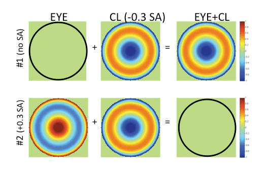
Fig. 3. The top row depicts an optically perfect wavefront corresponding to a hypothetical aberration-free presbyopic eye (left); the wavefront of a center-near soft multifocal contact lens with -0.3µm SA (middle); and the wavefront representing the sum of these two (right), providing a resultant eye plus contact lens residual amount of SA.
The lower row depicts the wavefront of a hypothetical presbyopic eye with +0.3µm of inherent SA (left); the wavefront representing the same center-near multifocal contact lens with -0.3µm SA (equal in magnitude, but opposite in sign to that of the eye) (middle); and the resultant optically-perfect wavefront representing the sum of the eye plus contact lens, leaving the eye well-corrected, but no residual SA aimed to expand the depth of focus of the wearer (right). |
Multifocal Contact Lens Design Limitations
The optical structure of all simultaneous image multifocal designs, as the name implies, leads to the combination of focused and defocused images appearing simultaneously at all times when viewing either distant or near targets. This can be seen in the simulated retinal image of Figure 2, which depicts the focused image corresponding to light passing through a “distance powered” area of the lens with the wearer viewing at distance; the defocused image obtained through the “near powered” area of the lens while the wearer remains looking at distance; and the result of these two images when the wearer simultaneously views through both of these areas of the lens (i.e., multifocal).
The decrease in perceived quality of vision reported by patients with simultaneous image multifocal lenses is most likely a direct result of the unavoidable presence of a defocused image in the combined multifocal image (Figure 2). The presence of these defocused images creates two primary changes in the multifocal retinal image: reduced contrast and a visible “ghost.” As can be seen in the simultaneous image quality simulation of Figure 2, small letters can be readily visible, but the overall contrast of the image is decreased and the defocused image can clearly be seen.
The effectiveness of these simultaneous image designs becomes limited by a few key optical principles. Specifically, the gradient power change of multifocal lenses from their center to periphery, which is designed to increase the depth of focus of the wearer, is most commonly a form of SA. Although nearly all single vision contact lenses also contain SA,6 multifocal lenses typically contain higher magnitudes of SA, with “higher add” designs containing the most.
Unlike the custom lens described above, which aims to correct the eye’s optics, in order for a multifocal lens to effectively expand the depth of focus of the presbyopic wearer, some level of residual eye plus contact lens SA is necessary. For example, if a patient’s eye did not have any SA, and a CN contact lens with SA (e.g., -0.3µm) was placed on it, the expected resultant eye plus lens SA would be -0.3µm, which might be expected to sufficiently expand the wearer's depth of focus (Figure 3).
Interestingly, most commercially available multifocal contact lenses are “center-near” (CN) designs. These have their most plus/least negative power at the lens center and least plus/most negative power at the periphery, and induce negative SA. Most human eyes, however, contain significant levels of positive SA.7-9 Therefore, on average, it is possible the eye may contain positive SA (e.g., +0.3µm), while the CN lens may contain a similar level of SA, but opposite in sign. In such a case, the multifocal CL does not generate a multifocal eye plus lens, but rather leaves the presbyopic eye with zero eye plus lens resultant SA and a good optical correction (at one single viewing distance), albeit not with an expanded depth of focus (Figure 3, bottom row).
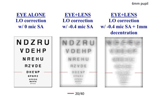
Obviously, any level of eye plus lens resultant SA may in itself degrade image quality. For example, Figure 4 shows a simulated retinal image of a fully corrected eye with no aberration and with -0.4µm residual SA as might occur with a CN lens. Notice the decrease in simulated perceived image quality caused by the SA. Furthermore, a contact lens correction may also mislocate on the eye relative to the pupil center. This mislocation of a correction that contains spherical defocus and SA induces other aberrations, such as prism and coma, which may further degrade image quality.
| |
| Fig. 4. The simulated retinal image of a typical letter chart of a sphere- and astigmatism-corrected presbyopic eye with no SA (left); the same corrected eye wearing a hypothetical center-near multifocal contact lens with -0.4µm SA (middle); and the same eye wearing the same contact lens, but when the multifocal contact lens is decentered 1mm on the eye, inducing other aberration (i.e., coma) (right). |
This induction of other aberration is in direct proportion to the amount of decentration and the amount of spherical defocus and SA contained within the lens.10 Specifically, decentration of a lens with higher levels of SA will generate higher levels of induced coma and poorer image quality. The right panel of Figure 4 demonstrates the simulated retinal image of the same SA-containing lens shown in the middle panel, when decentered 1mm. Notice the distinctly worse simulated perceived image quality due to the decentration-induced coma aberration. Such dramatic changes in image quality are not associated with decentration of monofocal lenses, and the magnitude of this decentration effect is proportional to the level of SA contained within the contact lens.
Minimizing Limitations
The principle described above provides insight that may be used to enhance practitioner success when fitting multifocal lenses. Specifically, in order to minimize the impact of multifocal lens decentration, lower levels of SA must be used. However, lowering the SA level, reduces the multifocality of the lens. This apparent “Catch-22” suggests that to achieve a desired level of multifocality in the eye plus lens combination, while at the same time minimizing sensitivity to decentration, patients should be fit with multifocals that add to, rather than subtract from the inherent SA of the eye.
For example, assume that 0.4µm SA has been found necessary for an optical design to effectively expand the depth of focus, and that the sign of this SA does not matter (e.g., positive or negative will have the same effect), and that our eye has roughly +0.2µm SA (as might commonly occur in a presbyopic eye).7-9 One option to meet the necessary goal of 0.4µm eye plus lens SA is to supplement the +0.2µm SA in the eye with +0.2µm SA in a center-distance multifocal contact lens.
|
Fig. 5. Assuming it has hypothetically been determined that a magnitude of 0.4µm of resultant eye plus contact lens SA is necessary to expand the depth of focus of a presbyopic eye that has +0.2µm inherent SA, two alternative solutions to this goal are described.
One option to meet the goal of 0.4µm eye plus lens SA is to supplement the +0.2µm SA in the eye with +0.2µm SA in a center-distance multifocal contact lens. In this case, the aberration that is induced within the contact lens is minimized, as well as the aberration induced when this lens decenters 0.5mm inferiorly and temporally on the eye, in turn maximally preserving the simulated image quality of this eye plus lens (left panel). Alternatively, however, if a center-near contact lens is used to achieve the goal, -0.6µm SA is required to achieve the necessary magnitude of 0.4µm eye plus lens SA. In this case, notice that, in the presence of 0.5mm inferior-temporal on-eye contact lens decentration, the simulated image quality is much reduced (right panel). |
In this case, the aberration that is induced within the contact lens is minimized, as well as the aberration induced when this lens decenters 0.5mm inferiorly and temporally on the eye. In turn, both of these together maximally preserve the simulated image quality of this eye plus lens (Figure 5, left panel). Alternatively, however, if a center-near contact lens is used to achieve the goal, -0.6µm SA is required to achieve the necessary magnitude of 0.4µm eye plus lens SA. In this case, notice that, in the presence of the same on-eye lens decentration, the simulated image quality is much reduced (Figure 5, right panel).
The above argument implies multifocal corrections can be improved by measuring/knowing the aberration structure of our patients’ eyes and the contact lenses we aim to use. Practically speaking, however, this strategy requires specialized equipment and may be time consuming. Therefore, a surrogate approach could be used based on population averages and published knowledge of lens designs. Because all presbyopic eyes may have significant positive SA,8,9 consider using an aspheric CD design to add extra positive SA to the eye. With this small amount of added positive SA, we aim to reduce the sensitivity to lens decentration, while still providing sufficient expansion of their depth of focus.
If this approach does not work, the eye may not be “average,” and it may have inherent negative SA. In this case, a low aspheric CN design may improve performance. Alternatively, if this approach does not work, this eye may have low amounts of SA altogether. In this case, a possible approach is to try a “higher add” design with increased levels of SA or to combine low amounts of defocus with low amounts of SA.11
In the future, it is hoped more contact lenses that use these design concepts will become available. For now, however the current report provides some insight of how to best use currently available designs to enhance fitting success.
Disclosure: Drs. Kollbaum and Bradley have received research funding from several industry partners, including Alcon, Bausch + Lomb, CooperVision and Vistakon. They also hold a patent application (US Patent Application 13/496,613) related to some of the concepts discussed in this article.
Dr. Kollbaum is an Associate Professor, Associate Dean for Research, and Director of the Borish Center for Ophthalmic Research at the Indiana University (IU) School of Optometry. He holds an OD, Masters in Clinical Research and a PhD in Vision Science from IU. He is also a Fellow of the American Academy of Optometry and the British Contact Lens Association. In his faculty position, he teaches didactically and clinically in the areas of contact lenses and optics.
Dr. Bradley is a Professor of Optometry and Vision Science at IU, and runs a visual optics research lab there. His interests are centered around visual perception and the impact of the eye’s optics on visual function.
1. Holden BA, Fricke TR, Ho S, et al. GLobal vision impairment due to uncorrected presbyopia. Archives of Ophthalmology. 2008;126(12):1731-1739.
2. Opticourier 2006; www.opticourier.com/1webmagazine/2006/02feb/content/contact_lenses/index.asp. Accessed March 1, 2006.
3. Chamberlain P. Proclear 1 Day Multifocal: A refreshing perspective for the multifocal lens wearer. Paper presented at: BCLA2012; Birmingham, England.
4. Richdale K, Mitchell GL, Zadnik K. Comparison of Multifocal and Monovision Soft Contact Lens Corrections in Patients With Low-Astigmatic Presbyopia. Optometry & Vision Science. 2006;83(5):266-273 210.1097/1001.opx.0000216098.0000262165.0000216034.
5. de Gracia P, Dorronsoro C, Marcos S. Multiple zone multifocal phase designs. Optics letters. 2013;38:3526-9.
6. Kollbaum PS, Bradley A, Thibos LN. Comparing the Optical Properties of Soft Contact Lenses On and Off the Eye. Optometry & Vision Science. 2013;90(9):924-936 910.1097/1001.opx.0000434275.0000493435.da.
7. Thibos LN, Bradley A, Hong X. A statistical model of the aberration structure of normal, well-corrected eyes. Ophthalmic and Physiological Optics. 2002;22(5):427-433.
8. McLellan JS, Marcos S, Burns SA. Age-Related Changes in Monochromatic Wave Aberrations of the Human Eye. Investigative Ophthalmology & Visual Science. May 1, 2001 2001;42(6):1390-1395.
9. Applegate RA, Donnelly IIIWJ, Marsack JD, Koenig DE, Pesudovs K. Three-dimensional relationship between high-order root-mean-square wavefront error, pupil diameter, and aging. J. Opt. Soc. Am. A. 2007/03/01 2007;24(3):578-587.
10. Guirao A, Porter J, Williams DR, Cox IG. Effect of rotation and translation on the expected benefit of an ideal method to correct the eye's higher order aberrations. J. Opt. Soc. Am. A. 2001;18(5):1003-1015.
11. Zheleznyak L, Sabesan R, Oh J-S, MacRae S, Yoon G. Modified Monovision With Spherical Aberration to Improve Presbyopic Through-Focus Visual Performance. Investigative Ophthalmology & Visual Science. May 1, 2013 2013;54(5):3157-3165.